此主题分为四个部分讲述Mesh相关技术.本章主题如下:

  • Create a grid of points. 创建由点构成的网格.
  • Use a coroutine to analyze their placement. 使用协程分析它们的位置信息.
  • Define a surface with triangles. 使用三角形来定义表面.
  • Automatically generate normals. 自动生成法线.
  • Add texture coordinates and tangents. 添加贴图坐标与切线.

此为本人阅读笔记不作为转载处理,详细还请参看原文. 原文地址

在此教程里我们将创建简单的网格与三角面.

复杂的外表之下是简单的网格.
Beneath complex appearance lies simple geometry.

Rendering Things 渲染物体

如果你想让某些物体在Unity中可见,要用网格.它可能是从其他程序导入的3D模型.它可能是程序生成的网格.可能是Sprite,UI元素,或者粒子系统.Unity就是如此使用网格.所有的屏幕特效也都是mesh渲染出来的.

如果你想使某3D物体可见,需要添加两个组件 mesh filter & mesh renderer .mesh render 用来配置这个mesh是如何渲染.

Creating a Grid of Vertices 创建网格顶点

这里有一个概念我要提出,关于顺时针与逆时针的.假定我们从Z轴方向看物体,只能看到顺时针连接顶点的面,反之也是.

顺时针与逆时针

演示三角面形成

在下面的代码里 有三处注释的地方演示了分别连接三顶点形成正方形的三种情况.只是链接顺序不一样但都是顺时针,所以都可以在Z轴正常看到.

1
2
3
4
5
6
7
8
9
10
11
12
13
14
15
16
17
18
19
20
21
22
23
24
25
26
27
28
29
30
31
32
33
34
35
36
37
38
39
40
41
42
43
44
45
46
47
48
49
50
51
52
53
54
55
56
57
58
59
60
61
62
63
64
65
66
67
68
69
70
71
using UnityEngine;
using System.Collections;

[RequireComponent (typeof (MeshFilter), typeof (MeshRenderer))]
public class Grid : MonoBehaviour
{
public int xSize, ySize;


private Vector3 [] vertices;

private void Awake ()
{
StartCoroutine (Generate ());
}
private Mesh mesh;

private IEnumerator Generate ()
{
WaitForSeconds wait = new WaitForSeconds (0.05f);

GetComponent<MeshFilter> ().mesh = mesh = new Mesh ();
mesh.name = "Procedural Grid";

vertices = new Vector3 [(xSize + 1) * (ySize + 1)];

for (int i = 0, y = 0; y <= ySize; y++) {
for (int x = 0; x <= xSize; x++, i++) {
vertices [i] = new Vector3 (x, y);
yield return wait;
}
}
mesh.vertices = vertices;

int [] triangles = new int [6];
//triangles [0] = 0;
//triangles [1] = xSize + 1;
//triangles [2] = xSize + 2;
//triangles [3] = xSize + 2;
//triangles [4] = 1;
//triangles [5] = 0;


//triangles [0] = 1;
//triangles [1] = 0;
//triangles [2] = xSize + 1;
//triangles [3] = xSize + 2;
//triangles [4] = 1;
//triangles [5] = xSize + 1;

//triangles [0] = xSize + 1;
//triangles [1] = xSize + 2;
//triangles [2] = 0;
//triangles [3] = xSize + 2;
//triangles [4] = 1;
//triangles [5] = 0;

mesh.triangles = triangles;
}

private void OnDrawGizmos ()
{
if (vertices == null) {
return;
}
Gizmos.color = Color.black;
for (int i = 0; i < vertices.Length; i++) {
Gizmos.DrawSphere (vertices [i], 0.1f);
}
}
}

绘制正方形算法

如下算法直接可以按照定义尺寸(xSize,ySize)渲染出正方形.算法优点绕,我这里简单说一下。

第一步,创建顶点列表 从(0,0) 开始计算.
第二步,因为一个正方形的面由两个三角组成,需要连线 3*2=6 次.每次循环内都渲染一个正方形.

绘制顺序

1
2
3
4
5
6
7
8
9
10
11
12
13
14
15
16
17
18
vertices = new Vector3 [(xSize + 1) * (ySize + 1)];
for (int i = 0, y = 0; y <= ySize; y++) {
for (int x = 0; x <= xSize; x++, i++) {
vertices [i] = new Vector3 (x, y);
}
}
mesh.vertices = vertices;

int [] triangles = new int [xSize * ySize * 6];
for (int ti = 0, vi = 0, y = 0; y < ySize; y++, vi++) {
for (int x = 0; x < xSize; x++, ti += 6, vi++) {
triangles [ti] = vi;
triangles [ti + 3] = triangles [ti + 2] = vi + 1;
triangles [ti + 4] = triangles [ti + 1] = vi + xSize + 1;
triangles [ti + 5] = vi + xSize + 2;
}
}
mesh.triangles = triangles;

如果一下子理解不了上面的算法,你可以先看看下面这种演示版:

1
2
3
4
5
6
7
8
9
10
11
12
13
14
15
16
17
18
19
20
21
22
23
24
25
26
27
28
29
30
31
List<Vector3> grids = new List<Vector3> ();
List<int> triangles = new List<int> ();

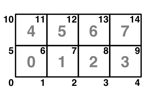
for (int y = 0; y <= ySize; y++) {
for (int x = 0; x <= xSize; x++) {
grids.Add (new Vector3 (x, y, 0));
}
}

mesh = new Mesh ();
mesh.vertices = grids.ToArray ();

for (int y = 0; y < ySize; y++) {
for (int x = 0; x < xSize; x++) {
int [] tri = new int [6];

tri [0] = grids.IndexOf (new Vector3 (x, y));
tri [1] = tri [4] = grids.IndexOf (new Vector3 (x, y + 1));
tri [2] = tri [3] = grids.IndexOf (new Vector3 (x + 1, y));
tri [5] = grids.IndexOf (new Vector3 (x + 1, y + 1));

for (int i = 0; i < tri.Length; i++) {
triangles.Add (tri [i]);
}
}
}

mesh.triangles = triangles.ToArray ();
mesh.RecalculateNormals ();//计算法线

Gizmos.DrawMesh (mesh, Vector3.zero, Quaternion.identity);

小贴士: 如何显示网格?

在Scene窗口Tab栏最左侧下拉列表中选择 Shaded Wireframe 即可。

Generating Additonal Vertex Data 生成额外顶点数据

我们的网格的光照很奇怪.这是因为没有给 Mesh 任何法线信息.默认法线方向为(0,0,1),这与我们需要的相反.

关于法线的物理性质我就不说了,相信各位中学物理都学过,入射角|法线|出射角

我们需要填充另一个法线矢量数组,也可以自动生成.调用如下方法.

1
mesh.RecalculateNormals();

生成UV信息.在生成网格的算法中插入uv计算代码.

1
2
3
4
5
6
7
8
9
10
11
vertices = new Vector3 [(xSize + 1) * (ySize + 1)];
Vector2 [] uv = new Vector2 [vertices.Length];

for (int i = 0, y = 0; y <= ySize; y++) {
for (int x = 0; x <= xSize; x++, i++) {
vertices [i] = new Vector3 (x, y);
uv [i] = new Vector2 ((float)x / xSize, (float)y / ySize);
}
}
mesh.vertices = vertices;
mesh.uv = uv;

生成切线信息,添加每个顶点的切线信息.

1
2
3
4
5
6
7
8
9
10
11
12
13
14
15
vertices = new Vector3 [(xSize + 1) * (ySize + 1)];
Vector2 [] uv = new Vector2 [vertices.Length];
Vector4 [] tangents = new Vector4 [vertices.Length];
Vector4 tangent = new Vector4 (1f, 0f, 0f, -1f);

for (int i = 0, y = 0; y <= ySize; y++) {
for (int x = 0; x <= xSize; x++, i++) {
vertices [i] = new Vector3 (x, y);
uv [i] = new Vector2 ((float)x / xSize, (float)y / ySize);
tangents [i] = tangent;
}
}
mesh.vertices = vertices;
mesh.uv = uv;
mesh.tangents = tangents;

小贴士:法线是如何工作的

法线贴图是在切线空间中定义的.这是一个围绕物体表面流动的三维空间.这种方法允许我们在不同的位置和方向上应用相同的法线贴图。
在这个空间,表面法线代表向上,但是哪一个方向是正确的?这是由切线定义的。理想情况下,这两个向量之间的夹角为90°。它们的交叉积产生了定义三维空间所需的第三个方向.事实上,角度往往不是90°,但结果仍然很好.
所以切线是一个3D向量,但是Unity实际上使用了四维向量。第四部分是不是−1就是1,它是用来控制第三切线空间的维数–向前或向后的方向。这有助于法线贴图的镜像,这通常被用在像双边对称的事物的3D模型中.unity着色器计算的时候需要我们使用-1。

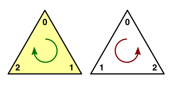
Normal maps are defined in tangent space. This is a 3D space that flows around the surface of an object. This approach allows us to apply the same normal map in different places and orientations.

The surface normal represents upward in this space, but which way is right? That’s defined by the tangent. Ideally, the angle between these two vectors is 90°. The cross product of them yields the third direction needed to define 3D space. In reality the angle is often not 90° but the results are still good enough.

So a tangent is a 3D vector, but Unity actually uses a 4D vector. Its fourth component is always either −1 or 1, which is used to control the direction of the third tangent space dimension – either forward or backward. This facilitates mirroring of normal maps, which is often used in 3D models of things with bilateral symmetry, like people. The way Unity’s shaders perform this calculation requires us to use −1.